Model Aircraft Light Controller
Design
As you may or may not know, aircraft flying at night are required to have navigational lights, configured as such. After flying my Hobby Zone Super Cub at dusk and comparing that experience with flying my ParkZone Night Vapour at night, it became clear that having lights on the aircraft would greatly increase usability.
That's how this project was born, an aircraft light controller. Or really, a pulsing circuit.
There are many ways to do this, the first two that come to mind are using a micro, or using a 555 chip. A micro requires a regulated supply, but can do some more interesting things, like changing the frequency based on battery voltage (notice the feature creep starting already). A 555 on the other hand requires no regulation and is very robust. Having a strange affinity for 555 chips that many share, I decided to go with that.
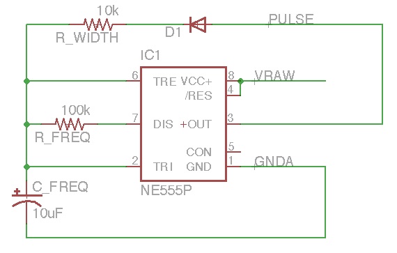
Here's the circuit:

This works by charging the capacitor through the 10k resistor. When it reaches a threshold level, the 555 output goes low. The 100k resistor then is the discharge path. When the capacitor discharges to the threshold point, the output goes high and charges the capacitor. This creates a pulsing waveform, with frequency around 1-2Hz (I didn't measure it) and very nice short pulse widths.
The 555 then controls a 2N3905 NPN transistor that drives the LEDs. Since the entire battery voltage is available, we can have more than a single LED in series, with a simple resistor to control current.
In my design I also added a place to have an "always on" LED so I could add landing lights. Not because they would be helpful, but just because they would look cool.
PCB Manufacturing
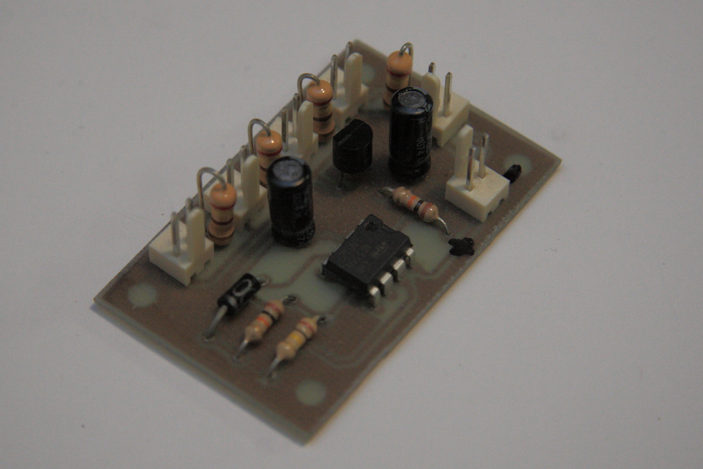
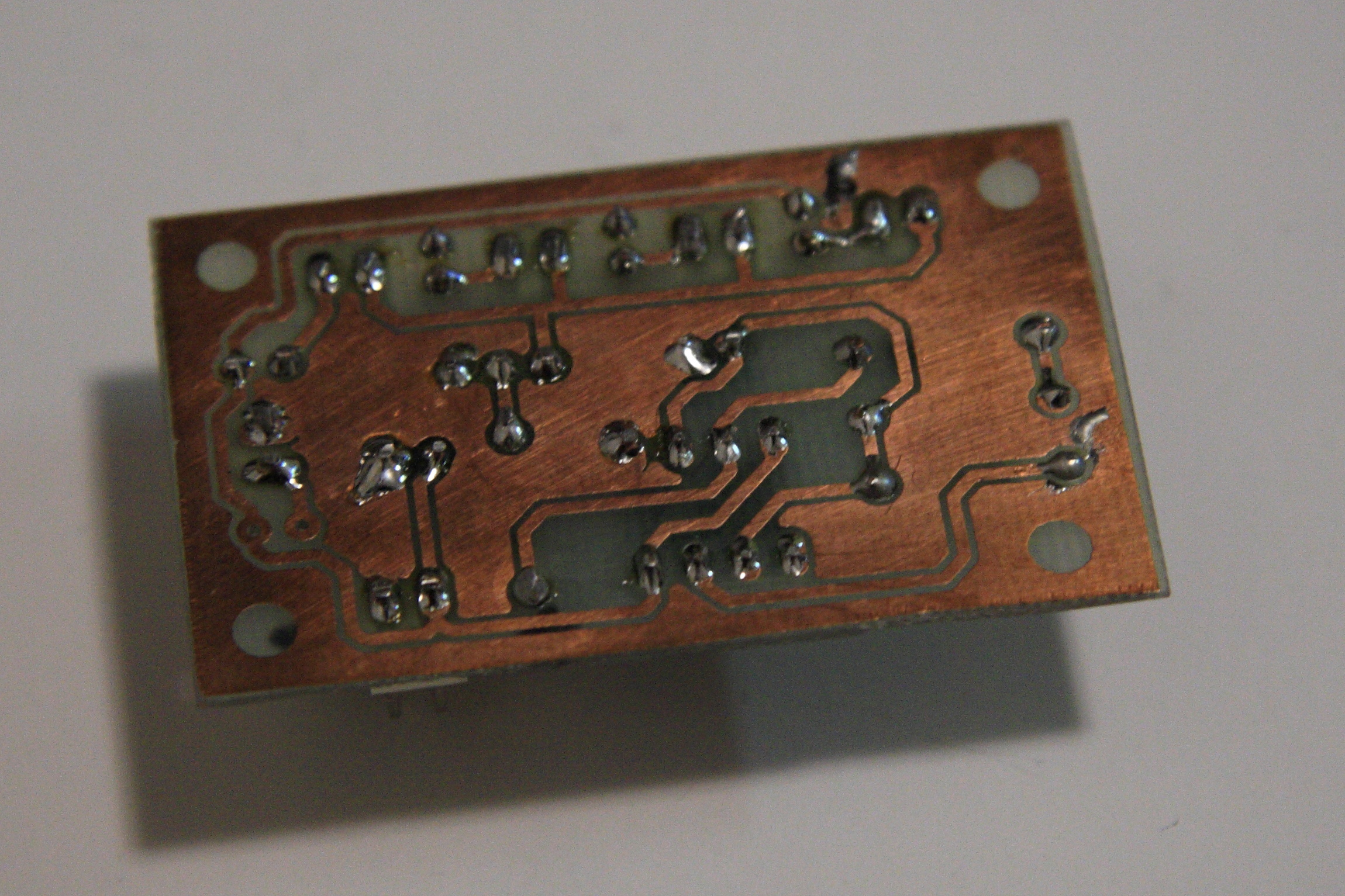
Here's a couple pictures of the finished PCB:


The PCB was designed using Eagle and etched using the "PCB Fab-in-a-Box" kit, which works great if you have the time and inclination to etch your own board. I used Feric Acid to etch away the copper. Needless to say, if you're planning on etching your own boards, use proper safety gear! Goggles, gloves, chemical apron, the works!
Circuit
The finished design can be found here. You will likely need to modify resistor values to fit your needs, different supply voltages can affect the frequency, different chips can have different voltage limits, etc. I was also very lazy with the resistors, I have to choose correct ones based on the LED forward voltage and the current I want going through them. That will come.
Eagle Files: Aircraft_lights
Tags: Electronics, Circuits